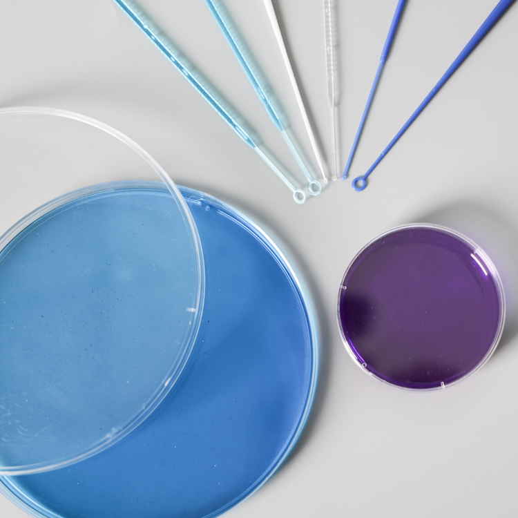
Inoculating loop and needle are instruments used for inoculation, serial dilution, aseptic sampling, transfer and microbial sample coating. Options include color-coded disposable consumables made of materials such as polymers, aluminum, and other metals. The disposable inoculating loops and the inoculation needles are made of non-toxic (USP VI grade) polystyrene material, which can provide users with a smooth surface of the inoculation loop for use in vaccines and diagnostic kits, pharmaceuticals and biotechnology.
Sterile Loop,Inoculating Loop And Needle,Disposable Inoculating Loops,Sterile Inoculating Loop,Sterile Disposable Inoculating Loops Yong Yue Medical Technology(Kunshan) Co.,Ltd , https://www.yypcr.com

Vortex pump principle and its application
Vortex pump works Vortex pump is a special type of centrifugal pump. The pump housing is perfectly circular with the suction and discharge outlets on the top of the pump housing. As for the internal structure of the pump and centrifugal pump is not the same. Impeller 1 is a disc, milling around the groove, into a radial arrangement, constitute the blade 2. There is a certain gap between the impeller and the pump casing 3 to form a flow passage 4. There is a partition 5 between the suction pipe connector and the discharge pipe connector. After the pump is filled with liquid, when the impeller rotates, due to the centrifugal force, the liquid in the vane groove will be thrown to the flow channel at a certain speed. In the flow channel with wide cross-sectional area, the liquid flow velocity slows down and some kinetic energy becomes static Pressure energy. At the same time, the inner side of the vane groove is thrown out by the liquid to form a low pressure, so the liquid with higher pressure in the flow channel can be re-entered into the vane groove to resume the pressure again by the centrifugal force, so that the liquid is inhaled through the suction port, Repeatedly through the vane groove and repeated vortex flow between the runner, and reach the exit, you can get a higher pressure head. The vortex pump should be irrigated before it starts. When the flow rate decreases, the vortex pump increases the pressure head and increases the power. Therefore, the vortex pump should not close the outlet valve before starting, and adjust the flow by bypass. Vortex pump flow is small, high pressure head, small size, simple structure. It is widely used in chemical production, suitable for small flow, high head pressure and viscosity of the liquid. The efficiency of the vortex pump is generally not more than 40%. Gear pump concept Gear pump concept is very simple, that is, in its most basic form is that the same size of two gears in a close-fitting rotation of the mutual engagement within the shell, the shell is similar to the internal "8" shape, two Gear installed inside, the outer diameter of the gear and both sides of the shell with the close fit. The material from the extruder enters the middle of the two gears at the suction port and fills this space, moving along the housing as the teeth rotate, finally exiting when the two teeth mesh. In the jargon, a gear pump, also called a positive displacement device, is like a piston in a cylinder that is squeezed out mechanically as one tooth enters the fluid space of the other tooth. Because the fluid is incompressible, the liquid and the tooth can not occupy the same space at the same time, so the fluid is eliminated. As a result of the continuous meshing of the teeth, this phenomenon occurs continuously and thus provides a continuous discharge at the outlet of the pump, the same amount of discharge per revolution of the pump. As the drive shaft rotates uninterruptedly, the pump discharges the fluid without interruption. Pump flow directly with the pump speed. In fact, there is a small amount of fluid loss in the pump, which makes it impossible to achieve a pump operating efficiency of 100% because these fluids are used to lubricate both sides of the bearing and gear, and the pump body can never be gap-free Can not make the fluid 100% discharged from the outlet, so a small amount of fluid loss is inevitable. However, the pump can still run well and still achieve efficiencies of 93% to 98% for most extruded materials. For fluids with varying viscosity or density in the process, the pump will not be affected too much. If you have a damper, such as a screen or a restrictor on the side of the outlet, the pump will push fluid through them. If this damper changes at work, ie if the screen becomes dirty, clogged, or the backpressure of the restrictor is increased, the pump will still maintain a constant flow until the mechanical limit of the weakest part of the device is reached (Usually fitted with a torque limiter). There is actually a limit to the speed of a pump, which depends mainly on the process fluid. If the oil is delivered, the pump can rotate at a high speed, but when the fluid is a high viscosity polymer melt When the body, this limit will be significantly reduced. It is very important to push the highly viscous fluid into the two-tooth space on the side of the suction port. If this space is not full, the pump can not discharge the exact flow rate, so the pv value (pressure × flow rate) is another limiting factor, and Is a process variable Due to these limitations, gear pump manufacturers will offer a range of products, namely different sizes and displacements (quantities discharged per revolution). These pumps will be matched to the specific application process to optimize system capacity and price.