1.3 Cabin 3D physical arrangement CATIA software can quickly establish the user's own coordinate system based on ship characteristics, hull structure, cabin definition, equipment unloading process path, etc., as shown in Figure 3. Based on this coordinate system, users can construct their own regional (segmented) design models. The biggest feature of this design model is that when a professional design task is carried out, other professional design results (ie entities, data, information, relationships, rules, etc.) can be referenced, correlated, and so that each major can be unified. In the design model, it is performed in parallel in different categories. 1.4 Two-dimensional schematic design and three-dimensional arrangement and component positioning of equipment and pipeline PID-Piping & Instrumentation Diagrams drives 3D equipment layout, piping layout and positioning and precise adjustment of various valve components and accessories. It is a unique technical feature of CATIA software. This feature constitutes a bridge between the detailed design and production design of the seamlessly connected ship piping system, ensuring the system principle, equipment connection, unit integration and theoretical direction of the two-dimensional schematic (PID) of the piping system in production. The most direct and scientific implementation of the actual design process. Using this schematic diagram, the user can drive the three-dimensional equipment placement in the diagram, automatically or manually discharge the piping path, position and arrange various valve parts, accessories, orientation adjustment, and detect the flow direction of the piping system to generate statistical reports. Taking the engine fuel supply system as an example, this paper draws a two-dimensional schematic diagram (PID), as shown in Figure 4, and drives the three-dimensional cabin equipment placement and piping layout, as shown in Figure 5. The two-dimensional symbols of the 1, 2, 3, 4, 5, 6, and 7 serial numbers in the two-dimensional schematic diagram of the piping system respectively represent the fuel oil supply unit, the fuel tank cabinet, the oil collecting cylinder, the generator, the main engine, the auxiliary boiler, and the fuel pump. . 1.5 Statistical summary report, processing form, layout drawing, installation drawing output The cabin that completes the three-dimensional physical arrangement is selected into the drawing working mode in CATIA, and the two-dimensional cabin layout map can be automatically projected. The user inserts a standard frame on the two-dimensional compartment layout, dimensioning (the system automatically displays the size), additional instructions, design signature, etc., and the installation layout is formed, as shown in Figure 6. This kind of real-time projection of 3D solids generates 2D drawings, which guarantees the one-to-one correspondence between 3D solids and 2D drawings, making the ship design work mode and operation means very flexible and simple. In addition, the cabin designer can also use the CATIA software's auxiliary simulation function to render the effect, and further use its four-dimensional browser function to provide the shipowner with a full range of multi-angle display cabin simulation effects. Previous page next page We are a professional bathroom Faucet accessories manufacturer and supplier in China. Here you can find high-quality products in a competitive price. Also we supply OEM service of products for you. Faucet Accessories,Angle Valve,Water Tap,Hand Shower Heshan Dingquan Sanitary Ware Industry Co., Ltd , https://www.dqoksanitary.com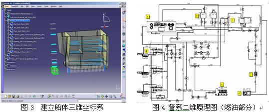
In addition, combined with the characteristics of the structure tree, the user can scroll through the structure tree, display, hide, delete, add, etc. any arbitrarily specified objects and their attributes in the design model; generate 2D views and arbitrary using 3D entities of CATIA software The function of the axonometric drawing is to generate various layout drawings and installation drawings. More importantly, users can perform real-time interference checks and integrated system balancing for each discipline in an integrated design model, providing a visual design pattern and operating tools for precision shipbuilding. In this paper, the piping fuel supply system in the engine room (ribs from 11 to 37) is taken as the actual measurement object, and its hull structure, equipment, piping and other functions are examined. 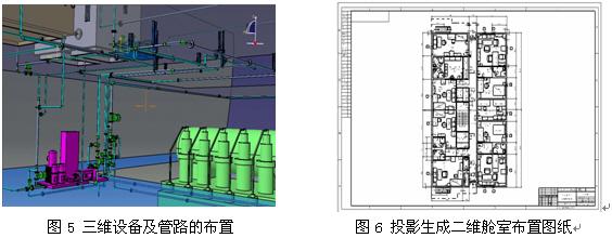
In addition, according to the design principles and physical commonalities of piping, ducts and electrical, CATIA software provides the “path (ROUT)†in the same design model, consisting of a two-dimensional schematic (PID), a schematic of the duct system and The electrical schematic drives the geometrical spatial orientation of the path pipes, ducts and cables with the same properties arranged in three-dimensional space. Therefore, when piping, air ducts, and electrical designers use the same attribute path to perform their respective path layouts, the path interference between the piping system, the air duct, and the electrical can be detected in real time. On the basis of interference inspection, comprehensive coordination and balance integration of pipelines, ducts, circuits and hull structures, ship equipment, etc., pipelines, ducts, and electrical designers can directly locate themselves on their own “pathsâ€. Place and adjust various parts. For example: various types of pipes, valve parts, accessories, instruments, pipe supports, etc. on the "path" of the piping system; various types of air ducts, fans, air ducts, duct hangers, etc. on the "path" of ventilation; electrical "path" Various types of cables, accessories, cable trays, etc. And to check whether the piping, air duct and cable system arranged in the three-dimensional space should be neglected by the designer and the individual valve parts, accessories, etc. are omitted.