Name : REDUCER Vinyl flooring (spc flooring,click spc flooring)
Market :Export to American,Canadian,European Market,Part Asia,Africa Countries.Australia Market
Warranty :10 years for commercial and 25 years for residential
Stone Plastic Composite vinyl flooring is more and more popular new style eco-friendly vinyl flooring. SPC rigid flooring is set apart from other types of vinyl flooring by its uniquely resilient core layer. This core is made from a combination of natural limestone powder, polyvinyl chloride and some stabilizers. REDUCER,PVC REDUCER,SPC REDUCER,WPC REDUCER JIANGSU PERFECT NEW MATERIAL TECHNOLOGY CO., LTD. , https://www.bffloor.com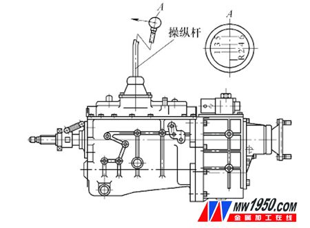
Figure 1 prototype prototype assembly structure 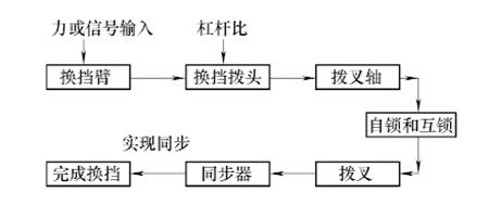
Figure 2 Scheduling operation flow diagram 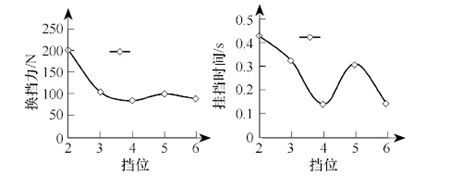
Figure 3 The relationship between shifting gear and shifting force and shifting time 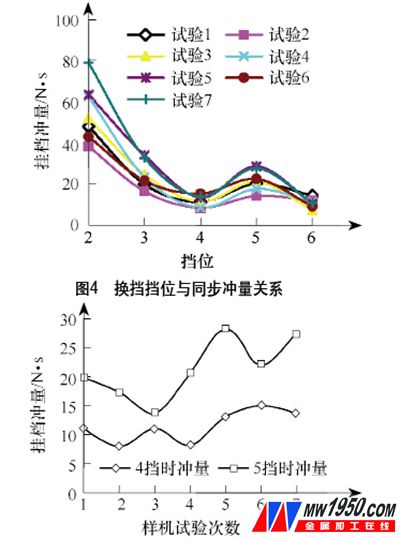
Figure 5 gear synchronous impulse curve 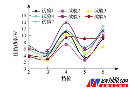
Figure 6 Relationship between power blocks 
Figure 7 Each work curve
Board Thickness : 4.0-7.0mm
Wearing Layer Thickness :0.3mm,0.5mm as regular
Surface Texture :Deep Grain,Wood Grain,Marble Grain,Stone,Carpet
Finish :UV-Coating
Installation :Click system(Unilin,Valinge)
Delivery Time :15-25 days
Size:6''*48''(150mm*1220mm)
7''*48''(182mm*1220mm)
9''*48''(230mm*1220mm)
9''*60''(230mm*1525mm)
Backing Foam :IXPE(1.0mm,1.5mm,2.0mm) EVA(1.0mm,1.5mm)
Density :2.07kg/m3
Surface :Wood Embossed,Deep Wood Embossed,Handscraped,Eir.
Usage :Bedroom,Kitchen,Basements,Home,School,Hospital,Mall,Commercial to use.
Features :Waterproof,Wear resistant,Anti-slip,Moisture Proof,Fireproof,durable, anti-scratch, anti-bacterail.
SPC vinyl is a luxury vinyl flooring option with a structurally rigid, 100% waterproof core. SPC is also known as rigid core vinyl, and we use these terms interchangeably. Rigid core engineered vinyl flooring is designed to look like wood or stone, but requires less upkeep.
This flooring is durable, waterproof, and perfect for DIY installation. It`s ideal for both home and commercial areas.
Research on shifting efficiency of commercial vehicle transmission
The demand for driving comfort of commercial vehicles is constantly increasing, and shift performance is one of the evaluation criteria for the quality of transmissions, which has attracted more and more attention. The shifting performance needs to focus on its handling comfort, the size and consistency of the shifting force, the smoothness of the shift, and the clarity and flexibility of the gear. This is also the main evaluation index for measuring the shift performance of the transmission.
The shifting performance of the traditional transmission is mainly improved from the design of the synchronizer and the design of the shifting mechanism. The shift lever, the top cover selection, the shifting mechanism, the shifting fork shaft and the shift fork, the self-locking and interlocking mechanism In-depth studies, such as synchronizers, which have a synergistic or separate effect on shift performance when the transmission is operating. The shift performance improvement not only requires the improvement of the design of each subsystem, but also the analysis, comparison and integration of the comprehensive performance. This paper obtains the shifting force between different assemblies and different gears through the test (see Figure 1 for the prototype structure). , shifting time and other data, systematically and comparatively test the transmission shift performance consistency requirements and power distribution, and determine the best working speed of the transmission through the comparison of work and power efficiency analysis of each gear shift. Position provides a new way of thinking and optimization for transmission shift performance.
Shift mechanism working principle
The manual mechanical transmission shifting mechanism mainly has two shifting modes, a pull plate type and a shift fork type. A shifting fork shaft shifting mechanism of a certain type of our company consists of a shifting arm, a shifting shaft, a shifting shifting lever, a shifting fork, a fork shaft, a guide block, a self-locking steel ball, a spring, an interlocking pin and a synchronizer. composition. The operation of the specific shifting process is shown in Figure 2.
Trial test
Four prototypes were tested and two bench tests were carried out. The purpose of this test is to study the gear shifting efficiency of the transmission when shifting gears. In the test, the shifting force of each gear during shifting of the transmission and the time used for shifting each gear are measured. Through theoretical comparison and analysis, the relationship between shifting force and shifting time and gear is determined (see Figure 3).
As can be seen from Figure 3, the transmission hangs 2 stops from the neutral, 3 stops in the neutral, 4 stops in the neutral, 5 stops in the neutral, and 6 stops in the neutral. As the gear increases, the shifting force and shifting time are also increased. The smaller and tend to be flatter, the shifting efficiency is more and more stable. The shifting force and the shifting time trend are basically the same. As can be seen from Fig. 3, the shifting time of the 4th and 6th gears is the shortest 0.1~0.2s, the shifting force is the minimum 90~120N, and the shifting of the 2nd and 3rd gears. Both the time and the shifting force are 2 to 3 times higher than the 4th and 6th gears. It can be concluded from the above data that the shifting force and shifting time of the transmission are directly different in each gear, and the efficiency distribution is not balanced, which is represented by a curve such as a periodic waveform.
Synchronous impulse is used to describe the cumulative effect of force on time during shifting. Due to manufacturing and assembly errors, the measured values ​​of each gear fluctuate within a certain range. As shown in Fig. 4, in this test, the synchronous impulse of the fourth gear is lower than that of the fifth gear. It can be seen from Fig. 5 that the cumulative maximum value of force versus time in these seven test prototypes is 30 N·s, and the minimum value is 14 N·s, which has twice the difference, which indicates that the test prototypes are completely changed. There is no steady state in the process of the gear, but the shift between the gears is leaping, which is unfavorable for the requirement of high shift efficiency. In addition, from the synchronous impulse map of the 4th and 5th gears in Figure 5, it is found that the 4th gear has a small shifting force, the shifting time is short, the synchronous impulse change is relatively gentle, and the synchronous impulse change curve of the 5th gear changes greatly. Irregular, as two adjacent gears, because there is no smooth connection, the shifting efficiency and operating feel will be reduced during the shifting process.
It can be seen from Fig. 6 and Fig. 7 that the total work input of each gear tends to be stable, which is satisfactory for the shifting system. Through the previous discussion of the shifting efficiency, the shifting force curve, the shifting time curve and the impulse curve are compared. It is found that the shifting power curve and the shifting time curve are in opposite states, that is, the shifting efficiency of the 4th and 6th gears is at The crests, while the 2, 3, and 5 gear shifts are relatively lower than the 4 and 6 gear shifting powers.
The fourth gear with higher shifting power is used as the reference standard, and the other shifting efficiency is divided by the shifting power of the fourth gear. Observe the shifting efficiency of the other gears from the fourth gear to illustrate the performance between the shifting gears. The degree of concentration. 2, 3, 5 block relative to the 4th gear shifting power, only 38% of the power is used to perform shifting, the shifting efficiency is unbalanced, and the fluctuation is large, which is unfavorable to the stability of the mechanism. By improving the design, process and other methods, including understanding the energy dissipation nodes of each shift, the work done by each shift shift tends to be equal, and different shift efficiency requirements are realized by different input force and time.
Conclusion
Through the test analysis, the manual transmission has a large change in the shifting force and shifting time of each gear during the shifting process. Each gear is unable to effectively balance the various blocking forces and time during the design, due to the adjacent gears. The change in force and time is large and affects the overall shifting performance of the transmission. From the shifting work and power efficiency analysis of each gear, it can be seen that when the transmission is in the high speed gear, the shifting efficiency is higher than the low gear power. Therefore, in the transmission shift performance design process, when paying attention to the design performance improvement of a single subsystem, the reasonable distribution of the power of each gear should also be systematically considered, find the energy loss nodes of each gear, and perform equal power design. The overall performance of the transmission tends to be consistent, reducing unnecessary power waste.