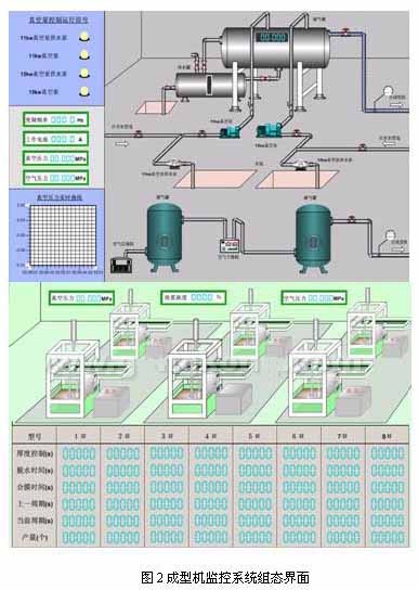
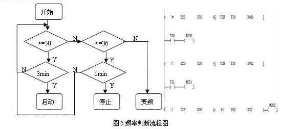
The pulp molding process was first used in the production of paper lunch boxes and paper trays in China, and has been widely used in the packaging of import and export products such as instrumentation and household appliances. Pulp molded products are a new type of environmentally friendly packaging materials with many advantages such as recyclability, environmentally friendly production process and low production cost. The production of pulp molded products is made of waste paper or pulp as raw materials. After pulping, pulping, forming, drying and shaping, it becomes a high-quality packaging product with environmental protection, shockproof and waterproof properties. In order to obtain the maximum benefit in the production of low-value paper products, further reduce the production cost, improve the production management level and quality management level of the entire pulp molding production line, and truly realize the transformation and optimization of the original production equipment. Centralized automatic control of each system in the complete production line. This article will focus on the control of important molding processes in the production line. The molding process consists of a water ring vacuum pump, a vacuum pump water supply pump, an air compressor, an air dryer, a molding machine, and the like. The function of the molding machine is to use the negative pressure to adsorb the prepared pulp on the pulp mold, and after pressing and dehydrating, the product is peeled off from the mold by positive pressure, and then proceeds to the next process. In the production process, the forming machine has high requirements for negative pressure stability, and generally requires a negative pressure to be maintained between -0.05 MPa and -0.06 MPa. The lower the negative pressure, the less pulp is absorbed by the mold of the molding machine, resulting in the product being too thin and the scrap rate increasing; the higher the negative pressure, the more likely the mold is clogged, affecting normal production, and on the other hand, the thickness of the product is over. Thick, wasting pulp and electricity. Since the number of molding machines has formed a certain scale, a centralized supply of negative pressure is adopted. The required negative pressure is generated by two sets of vacuum pump sets, and one set of vacuum pump sets includes a vacuum pump water supply pump and a water ring type vacuum pump. The original control system uses manual operation such as contactors and relays. The two groups of vacuum pump groups are independently controlled and operated at power frequency. Not only the control method lacks flexibility, but also the negative pressure fluctuation is relatively large, and the scrap rate is high. The production between each molding machine is relatively independent. Due to the different types of production, different process parameters need to be set, and the production volume is manually recorded and counted. In order to ensure the stability of the negative pressure supply, we have modified the original equipment by PLC and frequency converter, and adopted the PLC self-tuning PID function to realize the automatic switching and automatic frequency conversion control of the vacuum pump set. At the same time, the Modbus bus technology is used to communicate with the host computer easy-to-control (INSPEC) configuration software, which not only realizes the network real-time monitoring of product production, but also can automatically carry out production statistics, provide reports and print functions. The molding machine monitoring system mainly includes the upper computer configuration interface, communication protocol and PLC control system. The system structure diagram is shown in Figure 1. The configuration software is selected from the easy-to-control (INSPEC) developed by Beijing Jiu Siyi Automation Software Co., Ltd. INSPEC software supports simultaneous communication with different PLC devices. 2.1 Forming machine monitoring system configuration design and communication protocol Use the easy-to-control (INSPEC) configuration software to design the real-time monitoring screen of the host computer, as shown in Figure 2. Through animation to simulate real-time production conditions, the system is easy to observe and operate; after the database is prepared, the system will automatically save important production data, generate real-time curves, statistical output, and print reports; when the production process is abnormal, an alarm screen will pop up. , automatically shut down the system and prompt for related processing operations. The communication between the host computer and different types of PLCs uses different communication channels. The system sets up 1 channel to communicate with Delta PLC, 2 channels communicate with Emerson PLC; the same type of PLC uses addressing to distinguish The 8 molding machines respectively correspond to the addresses of 1 to 8; the bus selects the Modbus RTU mode, and the setting of the PLC communication port is consistent with the setting of the communication port of the upper computer. The system retains the original manual control, which is convenient for the backup function during system testing, maintenance, or when there is a problem with automatic control. The manual control and automatic control of the vacuum pump set are selected by a manual/automatic transfer switch. In order to save costs, in the automatic control mode, one inverter is used to control two motors, and the inverter switches between the two motors as needed. The start and stop operation of the motor is controlled by the PLC. On the output line of the vacuum tank, a negative pressure sensor is installed to obtain the actual negative pressure. The measured negative pressure is compared with a given target value, and the output frequency of the inverter is obtained by PID calculation. The whole set of devices constitutes a complete closed-loop control system, which can automatically adjust the output power of the motor according to the actual production needs, so as to achieve stable negative pressure and save energy and raw materials. The hardware configuration of the control system includes: Taian N2 series 220V/440V 22kw inverter, Emerson EC20 series programmable controller (PLC), Emerson EC20 series 8AD module, Emerson EC20 series 4DA module, negative pressure sensor, and air switch System breakers such as circuit breakers and lightning arresters also include contactors and relays. They are mainly used for relay output of PLC and switching between two motors. The principle block diagram of the system is shown in Figure 3: The negative pressure sensor is responsible for collecting the signal of the negative pressure in real time during the production process, and then sending the 4-20 mA current signal to the 8AD module of the PLC control system through the shielded twisted pair, and comparing with the target value set in the PLC, the difference is The value is sent to the PID calculation to obtain a control quantity, which is converted into a voltage signal of 0 to 10V by the 4DA module, and the rotation speed of the motor is changed by changing the output frequency of the frequency converter to realize automatic adjustment of the negative pressure pressure. In the automatic mode, the soft start of the motor is realized by the frequency converter, which can effectively reduce the impact of the starting current on the motor and prolong the service life of the motor. The two motors will operate in accordance with the frequency conversion time (we set it as 36 hours) and take turns as the motor for variable frequency operation. During the variable frequency operation of the motor, if the frequency conversion time reaches the specified time, in order not to affect the production, the motor will continue to operate in frequency conversion until the motor of the variable frequency operation is automatically converted at the next startup. Considering that the water ring vacuum pump has a lower limit operating frequency, the frequency lower limit of the frequency converter is set to 36 Hz, and the upper frequency limit is set to 50 Hz. The PLC first starts the motor running at variable frequency. If the motor runs continuously at 50Hz for more than a period of time (we set it as 3 minutes), the negative pressure still fails to reach the target value, the system will automatically start another motor at the power frequency, and delay the period. After the time, judge again to avoid frequent start and stop of the motor; if the frequency of the inverter is as low as 36Hz and exceeds a certain period of time (we set it as 1 minute), the system will automatically stop the other motor to prevent external interference and cause the motor to be wrong. action. The operating frequency of the motor can send the frequency output signal of the inverter to the 8AD module of the PLC through the shielded twisted pair. The program block designed in this system is mainly divided into the following parts: initial configuration, mainly the initialization settings of PLC expansion module 8AD, 4DA and the setting of characteristic parameters, as well as the setting of PID control parameters; according to the time of frequency conversion operation, Determining the motor of the variable frequency operation and the motor of the power frequency operation; according to the feedback signal of the negative pressure sensor and the set target value, performing PID calculation to obtain the control quantity of the frequency conversion running frequency; determining the running frequency, according to the judgment result, determining whether Start and stop power frequency running motor and variable frequency running motor running frequency; motor running signal, fault signal detection and over current protection, inverter fault signal and reset. Emerson EC20 series PLC programming software comes with PID instruction wizard, which changes the difficulty of PLC implementation of PID control algorithm. It can quickly and easily generate PID configuration program and PID control program, which reduces the burden of writing program. The following is a detailed description of several important parts of the program. PID control parameter tuning. The variable frequency control system selects the 0~2000 mode of the 4DA module corresponding to 0~10V mode, so it is necessary to set the output upper and lower limits of the PID control to be valid, and set the output lower limit value to 0, the output upper limit value is 2000, and the 4DA module. The input digital quantity corresponds to the blind area of ​​the control; the sampling time should be selected properly, and the sampling time is too short. The PID instruction cannot be executed. After field debugging, the sampling time we selected is 100ms; in order to smooth the measurement value, the input is filtered. The constant is set to 10%; the 10% differential gain can be selected to ease the output value to be drastically changed; the tuning of the control system PID parameters is continuously adjusted according to the real-time curve of the negative pressure, and finally the appropriate value is determined. Frequency conversion running time calculation and switching. The program flow chart and part of the ladder diagram are shown in Figure 4. D500, D501, D502 are the data registers held by power failure, D500 stores the frequency conversion running time of 36 hours, D501 stores the time of 18kw vacuum pump group frequency conversion operation, D502 stores the time of 22kw vacuum pump group frequency conversion operation. X2 and X4 are the frequency conversion operation signal of 18kw vacuum pump group and the frequency conversion operation signal of 22kw vacuum pump group. M30 is in automatic control mode. The M205's normally closed contact is connected to the 18kw vacuum pump set variable frequency start signal, and the M206's normally open contact is connected to the 22kw vacuum pump set variable frequency start signal. The result of the program operation will cause the M205 to generate a clock oscillation signal with a period of 72 hours, in which the first half of the first cycle is 0, that is, the motor frequency conversion operation of the 18kw vacuum pump set is first selected. Run frequency calculation. The program flow chart and part of the ladder diagram are shown in Figure 5. D22 is the frequency calculated by PID, D32 is the upper frequency limit set by the inverter, and D30 is the lower frequency limit set by the inverter. T30 and T31 use the on-delay timing command. Only when the frequency reaches the set value and continues for the set length of time D401 and D402, the coils M200 and M201 will be turned on. The coils M200, M201, and M202 correspond to the operations of starting the motor, stopping the motor, and controlling the variable frequency motor, respectively. 3 Conclusion In this paper, the automatic frequency conversion control of the vacuum pump set is realized by PLC and frequency converter, which changes the current situation of large negative pressure fluctuation and high scrap rate in the pulp molding production line; using the excellent networking function of the easy-to-control (INSPEC) configuration software, The real-time production data monitoring of the molding machine is realized conveniently and quickly. The actual results show that the system not only improves the response speed and production efficiency of the control system, but also saves raw materials and electric energy, making the system operation more reasonable, flexible and reliable.
Explore our large inventory of Komatsu final drives and Komatsu travel motors. Talk to a parts expert and find a best-priced, best-built Final Drive.
Komatsu Final Drive,Komatsu Final Drive Assy,Komatsu Travel Motor,Komatsu Travel Gearbox,Komatsu Final Drive Spare Parts,Komatsu Drive Parts,Komatsu Motor Jining Juheng Hydraulic Machinery Co., Ltd. , https://www.sdjuhengmachine.com
The hardware configuration and functional design of the system. The vacuum pump constant negative pressure control is realized by the PID self-tuning function. The use of easy-to-control (INSPEC) to achieve online monitoring of molding machine production, automatic statistical output and report generation. Practice has shown that the success of the system solves the problems of large negative pressure fluctuation, high energy consumption and high waste rate in pulp molding production, which improves work efficiency, saves resources, reduces production cost, and has good promotion value.
Key words: pulp molding machine; easy to control (INSPEC); constant negative pressure; monitoring system introduction
1 Analysis of the production process of pulp molding machine
2 Design of molding machine monitoring system 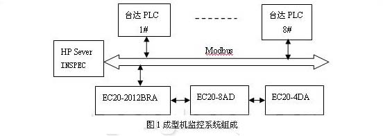
2.2 Vacuum pump frequency conversion control hardware design 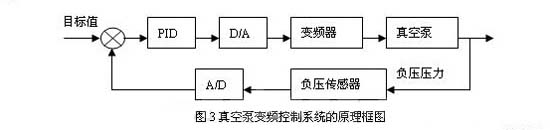
2.3 Vacuum pump frequency conversion control software design 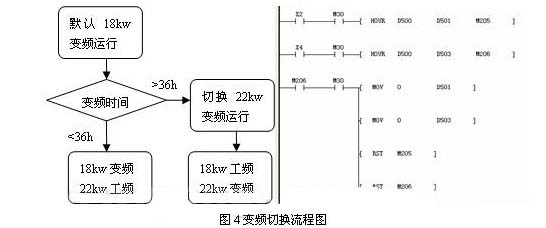
:
Unfortunately, it may sometimes be that case that your Komatsu machine will no longer move and you can therefore not continue working. The reason for this can be a worn final drive. You, of course, want your machine to start working again as soon as possible. The final drive must therefore be replaced as soon as possible.
With solutions available for over 70 Komatsu excavator models, we are sure to have the Komatsu final drive or Travel Motor you need. Our new JUHENG brand final drives and reconditioned OEM final drives are both excellent options that provide incredible performance and reliability at up to 70% off the cost of new OEM dealer pricing and yet still offer the peace-of-mind of that comes from purchasing a final drive from a respectable, long-standing final drive provider.
At JUHENG, our confidence in our products allows us to offer a 2-year warranty on new JUHENG Brand final drives and 6 month warranty on reconditioned final drives.
Komatsu Final Drive,Komatsu Final Drive Assy,Komatsu Travel Motor,Komatsu Travel Gearbox,Komatsu Final Drive Spare Parts,Komatsu Drive Parts,Komatsu Motor.
With solutions available for over 170 Komatsu excavator models, we are sure to have the Komatsu final drive or travel motor you need.long-standing final drive provider.and 15 month warranty on final drives.
Application of Easy Control (INSPEC) Configuration Software in Monitoring System of Pulp Molding Machine
Summary:
0 times
Window._bd_share_config = { "common": { "bdSnsKey": {}, "bdText": "", "bdMini": "2", "bdMiniList": false, "bdPic": "", "bdStyle": " 0", "bdSize": "24" }, "share": {}, "image": { "viewList": ["qzone", "tsina", "tqq", "renren", "weixin"], "viewText": "Share to:", "viewSize": "16" }, "selectShare": { "bdContainerClass": null, "bdSelectMiniList": ["qzone", "tsina", "tqq", "renren" , "weixin"] } }; with (document) 0[(getElementsByTagName('head')[0] || body).appendChild(createElement('script')).src = 'http://bdimg.share. Baidu.com/static/api/js/share.js?v=89860593.js?cdnversion=' + ~(-new Date() / 36e5)];